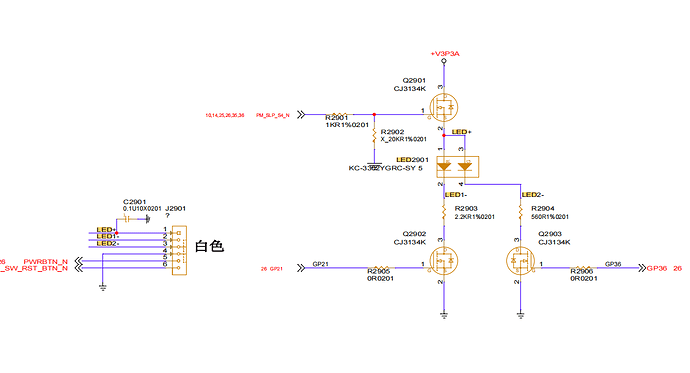
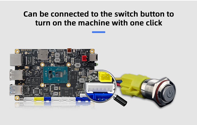
Expansion pin to add start switch based on user feedback.
https://wiki.youyeetoo.com/en/x1/IntroductiontoDevelopmentBoard
Previous Version
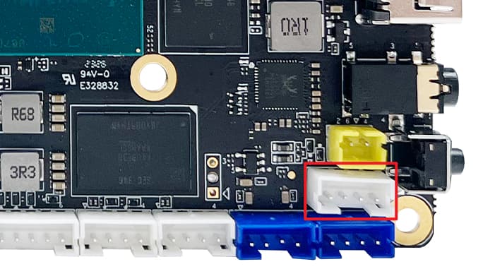
New Version
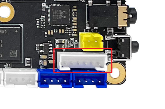
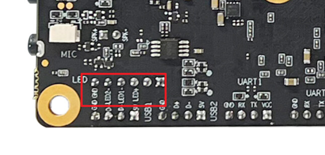
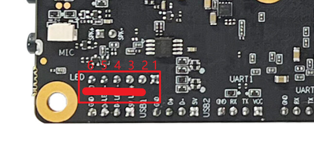
The silkscreen above is wrong, please the real pinout diagram.
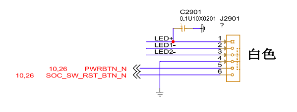
| Num |
Function |
Mark |
| 1 |
LED+ |
|
| 2 |
LED1- |
|
| 3 |
LED2- |
|
| 4 |
GND |
|
| 5 |
PWRBTN_N |
ON/OFF Power Signal |
| 6 |
SOC_SW_RST_BTN_N |
Reset Signal |
1 Like
If you want to invoke this start button in an older version, and also have soldering skills, then check out the schematic for the older version and refer to this step-by-step procedure to complete the modification.
Alterations are risky, so please think it over.
Alterations are risky, so please think it over.
Alterations are risky, so please think it over.
Step:
- Check the SCH V1 and bitmap V2 files of X1
- Find the SCH of the switch
- Determine the location of the components from the bitmap.
- Verify that pins 2 and 3 of the switch are on when pressed and off when released by using the on/off position of the multimeter.
- Finally, solder the wires to the corresponding circuits on pins 2 and 3 to extend the startup switch.
Also, meeting your needs requires soldering on the X1, which can easily cause damage if your skills are not good.
Alterations are risky, so please think it over.
Alterations are risky, so please think it over.
Alterations are risky, so please think it over.
Is this applicable to the R1 as well? Also, can the same concept be used to reset the power?
Please refer to the schematic diagram.


