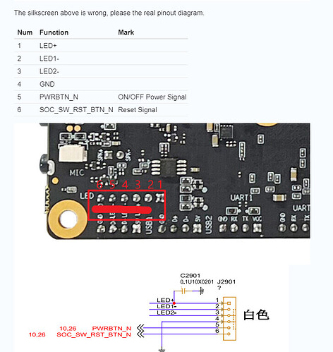
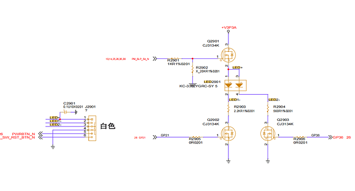
Has anyone been able to get the power/reset/led pins to work on the new V3 board? Been playing around with these and can’t seem to get it to work with the normal short/long push. Not much documentation available other than its existence and some schematics. Not to mention the schematics and connection labels on the boards are not the same. Schematics label pins 1-3 as LED, 4 as ground, 5 and 6 for power reset. The back of the board labels pin 1 as ground, 2-4 as LED, 5-6 power and reset. What I want to do is use a Power and Reset button to control the board similar to what you see in a PC case. These controls, as well as the LED are all two wires each. The X1 pin out does seem to follow that pattern. Any help or clear explanation would be greatly appreciated.
I missed that. Thank you. Still curious as the pin out doesn’t resemble standard LED and PWR/RST. Typically each function and LED gets its own isolated +/- connection. Looks like you get either green/or red LED and Reset or Power. Not all or both.
Check out the full SCH.
Due to the compact version, we scaled down the GND and generic computer motherboard boot keys are not the same.
You can adjust it according to your needs.
Or you can provide the link or specification of the switch being used and we provide wiring suggestions to you.
I am just going to go with green pwr led, and pwr button. I substitute POE control for a reset switch. As it stands right now all is working as it should. Appreciate your help and answers.

