Hi,
I am using the ESP32 to control the speed rotation, but I using 30khz with 46% of duty cycle and the system does not change the speed, I would like to know how to control the speed and stop the motor, could you please explain to me step by step how I do that? I am using Arduino IDE environment to program the ESP32.
Thanks
Plz check out our wiki.
FHL-LD19 WIKI
The LD19 has a motor driver with stepless speed regulation, which supports internal speed control and external speed control. Whenthe PWM pin is grounded, the default is internal speed regulation, and the default speed is 10±0.1Hz.
For external speed control, a square wave signal needs to be connected to the PWM pin, and the start, stop and speed of the motor can be controlled through the duty cycle of the PWM signal.
Conditions for triggering external speed control:
a. Input PWM frequency 20-50K, recommended 30K;
b. Duty cycle is within (45%, 55%) interval (excluding 45% and 55%), and at least 100ms continuous input time.
After the external speed control is triggered, it is always in the external speed control state, and the internal speed control will be restored unless the power is turned off and restarted; at the same time, the speed control can be performed by adjusting the PWM duty cycle. Due to the individual differences of each product motor, the actual speed may be different when the duty cycle is set to a typical value. To accurately control the motor speed, it is necessary to perform closed-loop control according to the speed information in the received data.
Note:
When not using external speed control, the PWM pin must be grounded.
Steps:
1. Trigger the external speed control function first
2. PWM pin is low, the motor stops. If high, motor full speed.
3. If you need to control the speed accurately, you need to use the feedback of the “radar speed” parameter for closed-loop control.
Thanks for your response.
Based on your recommendation, I applied the PWM pin to LOW and after I applied energy in radar. I expected the instrument not start, but the system running in normal operating.
Please, I would like a step by step the procedure for repeat the operation to have the system in standby mode, because if I achieve this I will know how I need to do for control the speed motor.
If possible you do a video with this procedure I appreciate.
Thanks.
Cristian Cecconello
- Make sure that the frequency and duty cycle of the ESP32’s PWM pin output meet the requirements (20-50K Hz , 50% duty cycle, 100ms).
You can confirm this first with an oscilloscope or LEDs or some analog platform.
-
Set up a function to control the pin to continuously output PWM for 1 Second, and then set the pin to low, 1 Second.
-
Connect the lidar and ESP32, and start it up. (Make sure ESP32 and lidar use the same GND)
-
See what happens to the lidar.
@Cristian_Cecconello did @CharlesChen’s approach solve your problem?
I apologise for bumping this old thread, but I’m asking because I’m having the same issues trying to control the motor from a Pi 4.
The testing on my end went a bit like so:
-
pin linked to GND at all times, lidar spins with internal speed control at 10 hz
-
pin linked to 30khz 50% duty PWM, lidar switches to external control, speeds up to about 11 hz, if I pull the pin low at this point, the motor does not react, continues to spin at 11 hz
-
increasing the duty cycle seems to speed it up to about 14 hz max
-
lowering the duty cycle reduces it to a min of about 4 hz, at speeds lower than that my ROS driver stops publishing data so I’m not sure if there’s still anything being sampled and sent or not
-
lowering the duty cycle to only a few percent stalls the motor, so the indicator light only flashes in the same position repeately, presumably still gathering data
Even if I literally set it to PWM mode, take the motor speed input wire, and unplug it, plug it directly into one of the GND pins on the Pi the lidar does not react at all. It seems that it only treats valid PWM signals as something it should act upon, it’s really weird.
Now if setting the duty cycle to 1% to stop the motor to was the workaround that would be fine by me… but what’s problematic is that regardless of the motor speed the lidar continues to draw about ~200 mA at all times, even when stationary. Since the main point of turning it off during idle periods is to reduce power consumption, all of these shenanigans don’t really help at all. Any ideas?
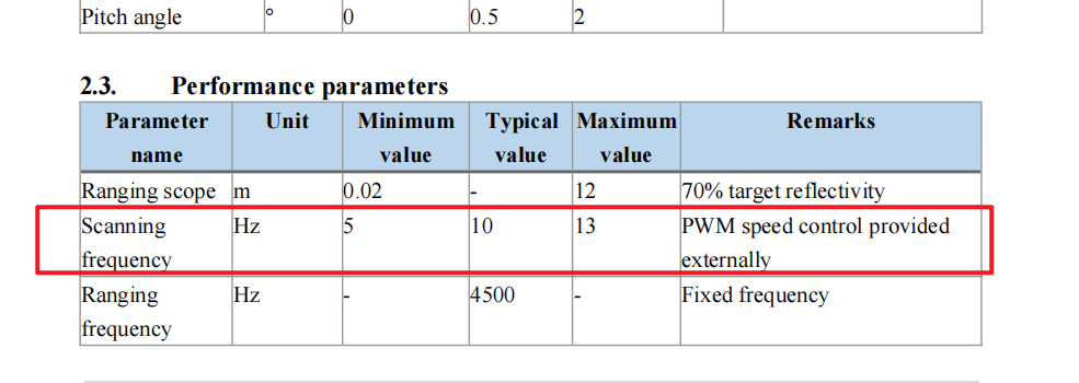
Refer to datasheet and wiki. FHL-LD19 has a speed regulation in the range of 5-13Hz, please do not exceed this range.
Since the product is powered all the time, there is a relatively high quiescent current even if the motor is stopped.
You could try switching the power supply on and off via a MOS or transistor control.
Control the power consumption by disconnecting the power.
You can search online for how to implement .
1 Like
Ah alright, thanks for the confirmation.
You could try switching the power supply on and off via a MOS or transistor control.
Yeah that was my second thought, I do have some XY-MOS boards laying around that should do the job, but I was hoping I could avoid the extra complexity.  I foresee some issues with the uart connection dropping in and out confusing the ROS driver, but that can probably be fixed.
Another option might be to use it through the Pi’s USB ports and then turn the entire USB hub off to disable the lidar I guess.
My idea was to cut the power supply from the USB adapter board to the lidar.
 as a Switch")