Connecting the Lidar to a windows machine

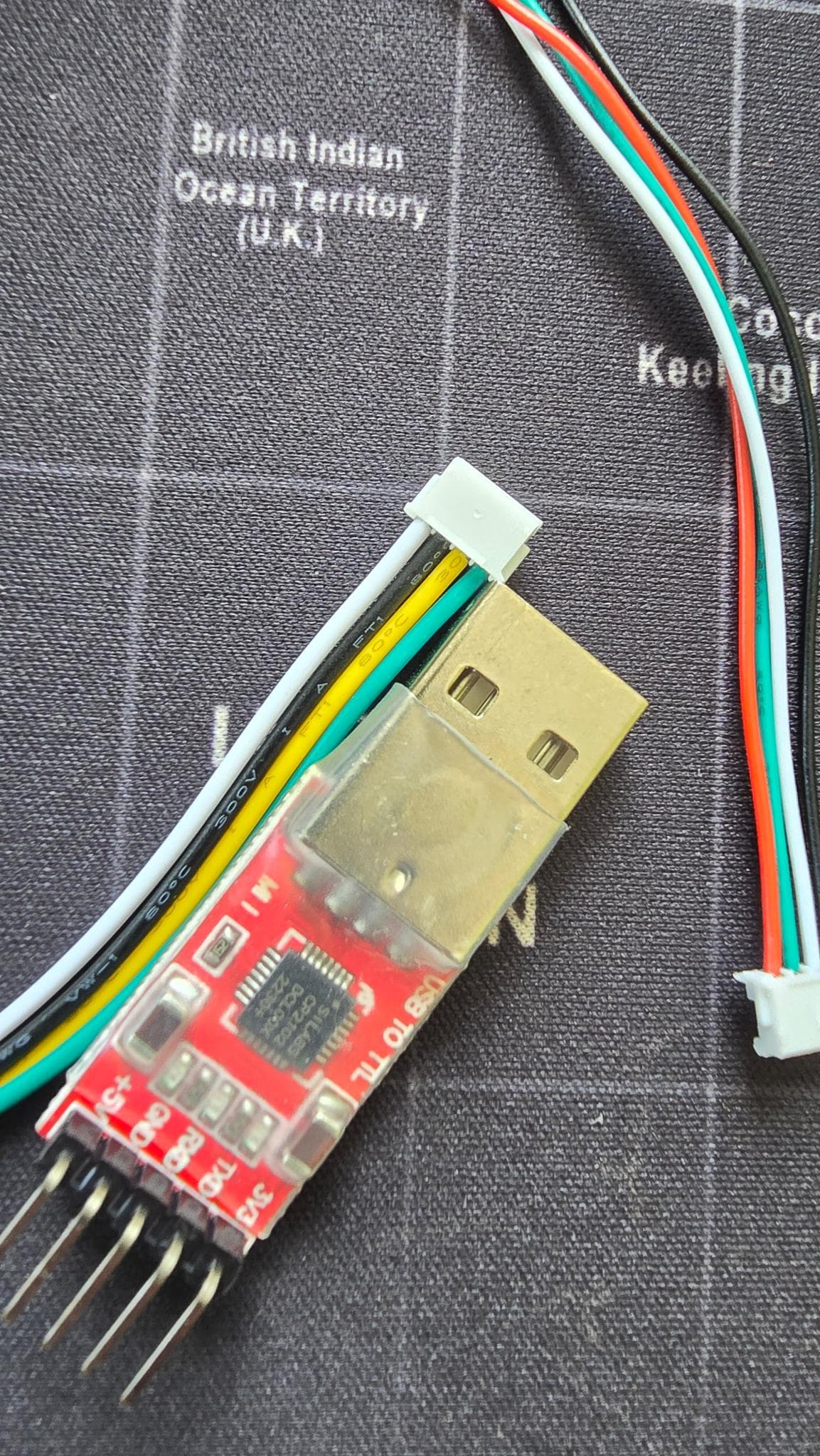
Hello, I recently bought a LD19+ / STL-27L lidar on Amazon. It arrived with two cables, one long (1 - >black, 2 → white, 3 → green and 4 → red) and a short one (white, black, yellow, green). I also received a USB to USART adapter CP2102 with 5 pins (+5V, GND, RXD, TXD, 3V3). I attached a picture of the wires and adapter.

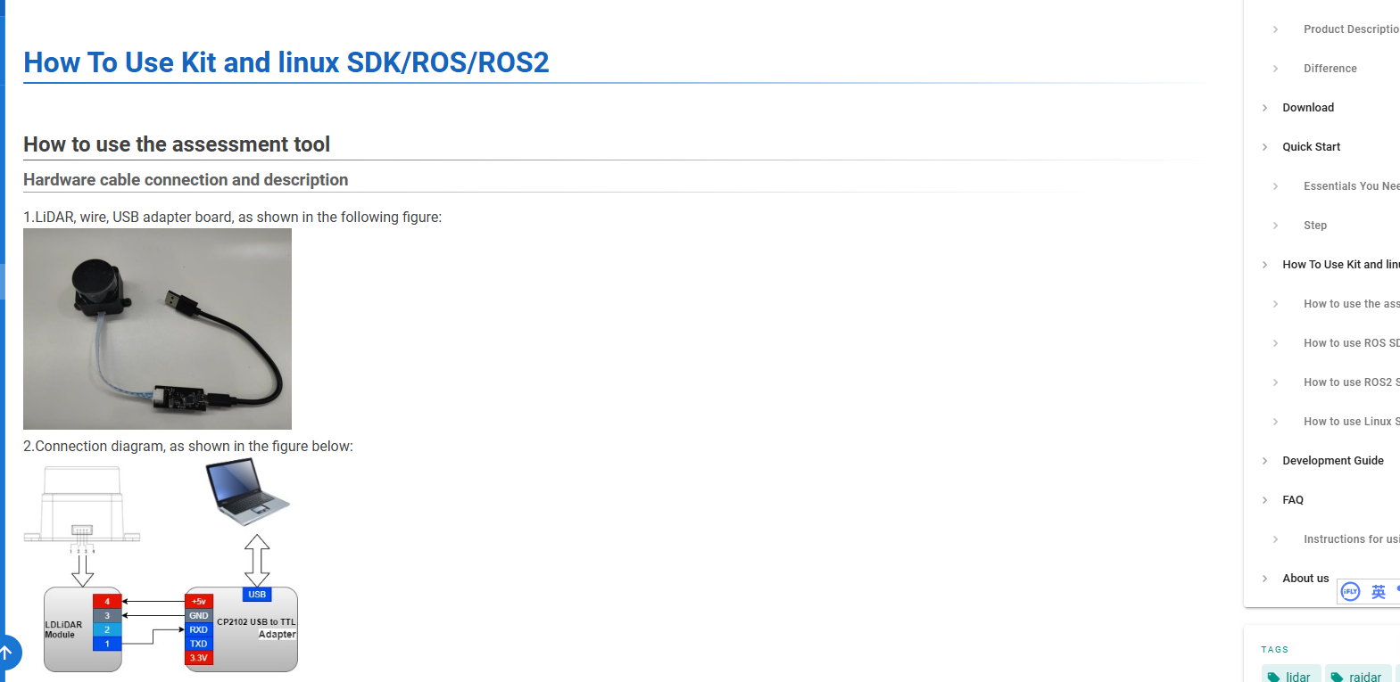
Before I try to connect and risk damaging something, I have a simple question: What wire goes where? I looked everywhere on the wiki and I cannot find any useful information .

Thank you for your help in that matter.

About wiring:

I’m stuck with this lidar stl27l. Beside the “demo” examples for Linux in the sdk files, is there a working example of code running on a raspberry pi that controls the lidar through the PWM input to start, stop and change the speed and receives the serial data at 900k bps?
I’ve spent a lot of time going through the documentation I could find anything that helps.
Thanks you!

Instructions on Motor PWM Speed Regulation

  • Supported Speed Regulation Modes
    • The motor driver of LD19 has a stepless speed regulation function, supporting both internal speed control and external speed control.
  • Internal Speed Control
    • When the PWM pin is grounded, internal speed control is used by default, and the default speed is 10 ± 0.1Hz.
  • External Speed Control
    • Control Method: A square - wave signal needs to be connected to the PWM pin. The start, stop, and speed of the motor can be controlled through the duty cycle of the PWM signal.
    • Trigger Conditions
      • a. The input PWM frequency should be in the range of 20 - 50K(LD19 P & LD19 Plus use 0.5 ~1.5Khz), with 30K (LD19 P & LD19 Plus: 1K ) being recommended.
      • b. The duty cycle should be within the interval of (45%, 55%) (excluding 45% and 55%), and the continuous input time should be at least 100ms.

Please check our wiki.