Soft magnetic and hard magnetic calibration
After completing the installation of the WHEELTEC N100 module, soft magnetic and hard magnetic calibration need to be performed if the environment magnetic field is fixed but with magnetic interference, or the geographical location has changed significantly. Find a relatively open space without interference, connect the module to the computer and open the upper machine software. Please stay away from interference sources as much as possible in front of the computer. Follow the steps below:
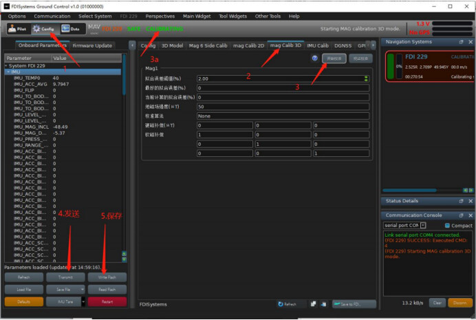
STEP1: Click config
STEP2: Click mag Calib3D to open the 3D magnetic calibration mode. A fitting error threshold can be set, such as 2% in the figure below, which means the calibration parameters will take effect only when the calibration error is less than 2%.
STEP3: Click “Start Calibration”. You can also observe that the system running mode changes from “NAVIGATION” to “Calibration” mode as shown in figure 3a. Draw figure 8 in the air with the module, do not move too fast, about 3-5s to complete one figure 8.
STEP4: After calibration is finished, click the “Transmit” button in the above figure to send parameters.
STEP5: Click the “writeFlash” button to save the parameters.
After calibration is complete, during the calibration process, the system will automatically adjust the algorithm accuracy to LOW, MID and High levels. Meanwhile, the soft magnetic and hard magnetic parameters as well as the earth magnetic field intensity will be calculated and displayed in real time. When the system status in figure 3a changes from Calibration back to NAVIGATION mode again, the calibration is finished. The condition for calibration to end is that the best fitting error of fitting is less than the set fitting error threshold.
If the status has not changed from Calibration to NAVIGATION mode, continue drawing figure 8 in the air. If it has not finished after 20 seconds, this is because the incorrect environmental magnetic field interference and improper movement have caused too large a fitting error. You can click the Calibration End button and restart the calibration process. Generally, the entire calibration process takes about 10s. If you are not satisfied with the calibration accuracy, you can click the Start Calibration button again to repeat the above steps for recalibration.
Leveling and parameter import/export
When using the WHEELTEC N100 module, there may be a situation where the output data is biased. For example, if the pitch and roll angles output are not zero, it indicates that there is an installation error angle between the module and the installation plane, and leveling of the system is required. Connect the module to the upper computer and operate in the config interface.
IMU Tare: This function has an arrow on the right side. Click the arrow to display the interface as shown in the figure below:
Level: Coordinate system conversion button. Place the module stationary and click this button for the upper computer to automatically calculate the size of the installation error angle, and convert the module coordinate system to the installation plane coordinate system through the built-in rotation matrix algorithm of the module. Click Write Flash after to save the parameters.
Acc Tare: Accelerometer tare button. The theoretical length output by the accelerometer when the module is stationary is 1g (about 9.8m/s^2). If the actual length output by the accelerometer differs greatly from 1g, this button can be used to recalibrate the accelerometer zero bias to return it to around 1g. Note that the module must be in a horizontal stationary state before clicking this button, and click Write Flash after to save the parameters.
Gyro Tare: Gyroscope tare button. The function of this button is to recalculate the static zero bias of the gyroscope, so that the gyroscope three-axis angular velocities subtracted from the zero bias return to near zero. This button must be operated when the module is stationary, otherwise the calculated zero bias will be incorrect, leading to attitude drift. If drifting attitudes are found when stationary, it is generally due to incorrect calculation of the gyroscope static zero bias. It is recommended to click this button for recalibration, and click Write Flash after to save the parameters.
Level + Gyro (Default): The function of this button is equivalent to clicking the Level button once and then clicking the Gyro button once.
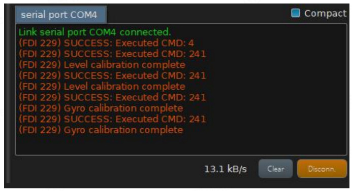
After completing the calibration correction, the following is output in the lower right corner log of the upper machine:
Why does the attitude keep drifting after the module is powered on each time, even though the module is stationary?
Answer: The root cause is most likely that the static zero bias of the gyroscope calculated during module startup is incorrect. Here are the steps to resolve it:
Make sure the module is stationary and power it on again, observe if the attitude is still drifting at this time.
If the attitude is still drifting, click the Gyro Tare button under stationary conditions to recalculate the static zero bias of the gyroscope, then click the write flash button to write it. See above for the function explanation of this button.
If the attitude is still offset after step 2, check if there is a changing magnetic field near the module (when the magnetometer switch is on), or if the surrounding temperature changes drastically. The former will cause drift of the heading angle, and the latter will cause changes in gyro zero bias, as temperature is the main reason for gyro zero bias changes.
If the problem still cannot be resolved after the above steps, contact our technical staff for communication and discussion.
It should be noted that the AID_GYO_TURN_ON_TARE_ENABLED switch in the FDIGroundStation SPKF fusion switch (lower left corner) of the upper computer is enabled by default, which automatically calculates the static gyro bias upon power-on. The module needs to be stationary during power-on. If the environment does not allow stationary startup, disable this switch to avoid attitude drift after power-on.